Dragon. My animatronic project.

I've posted some questions and comments before, but this will be the first real post about the full project.
I have been working on a dragon head and neck (so far). And, like a lot of other people, mine will be a long term project. I'll try to update as often as I can.
On to the project, and my progress so far!
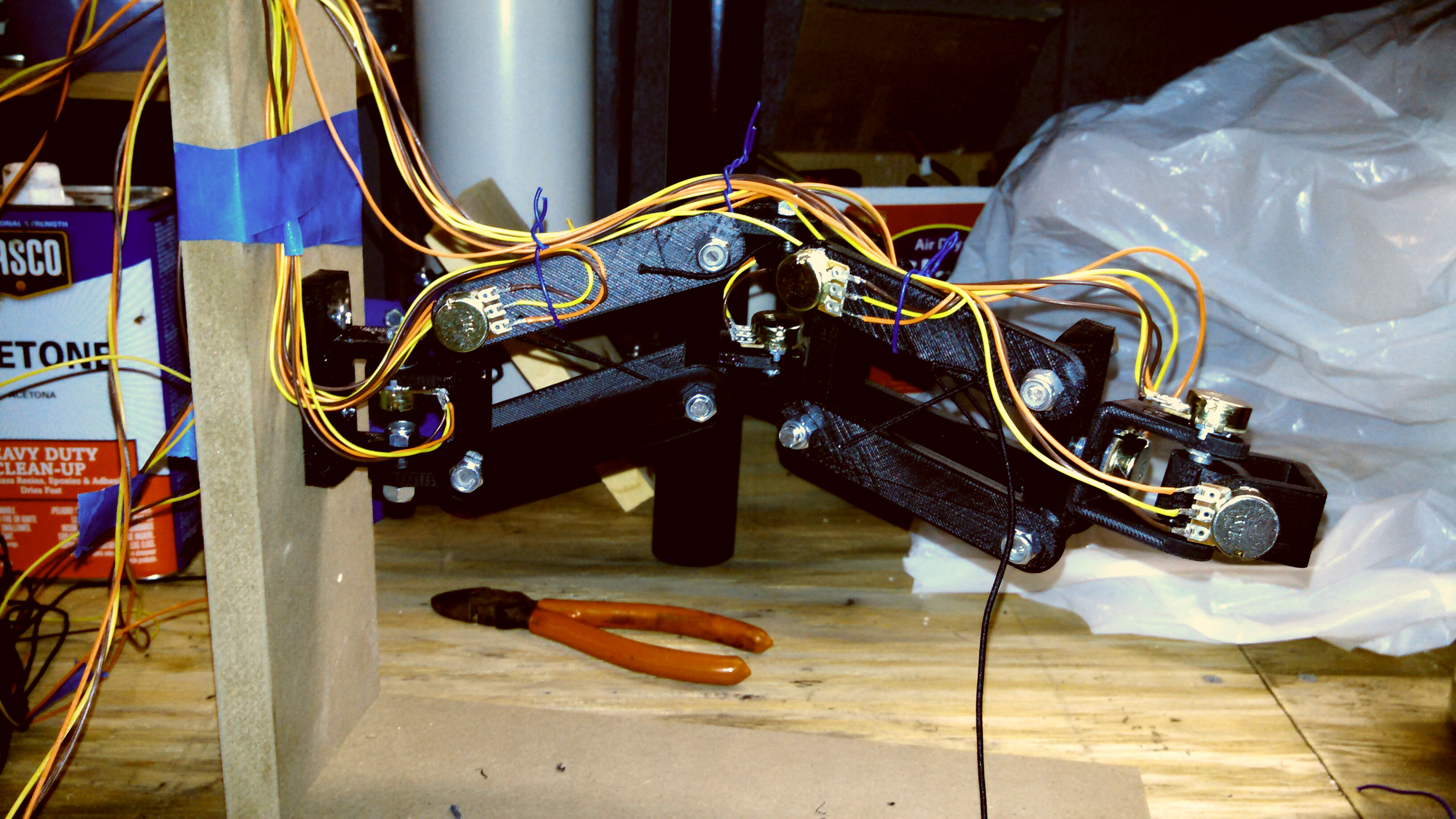
This is the neck. 2 vertical, and 2 horizontal hinge points, and a 3 axis plate to mount the head to. All of the hinge points, and the universal joint plate, are cable driven and counterbalanced with springs. The rotating axis is driven by a servo and gear drive. Still a lot of assembly to do!

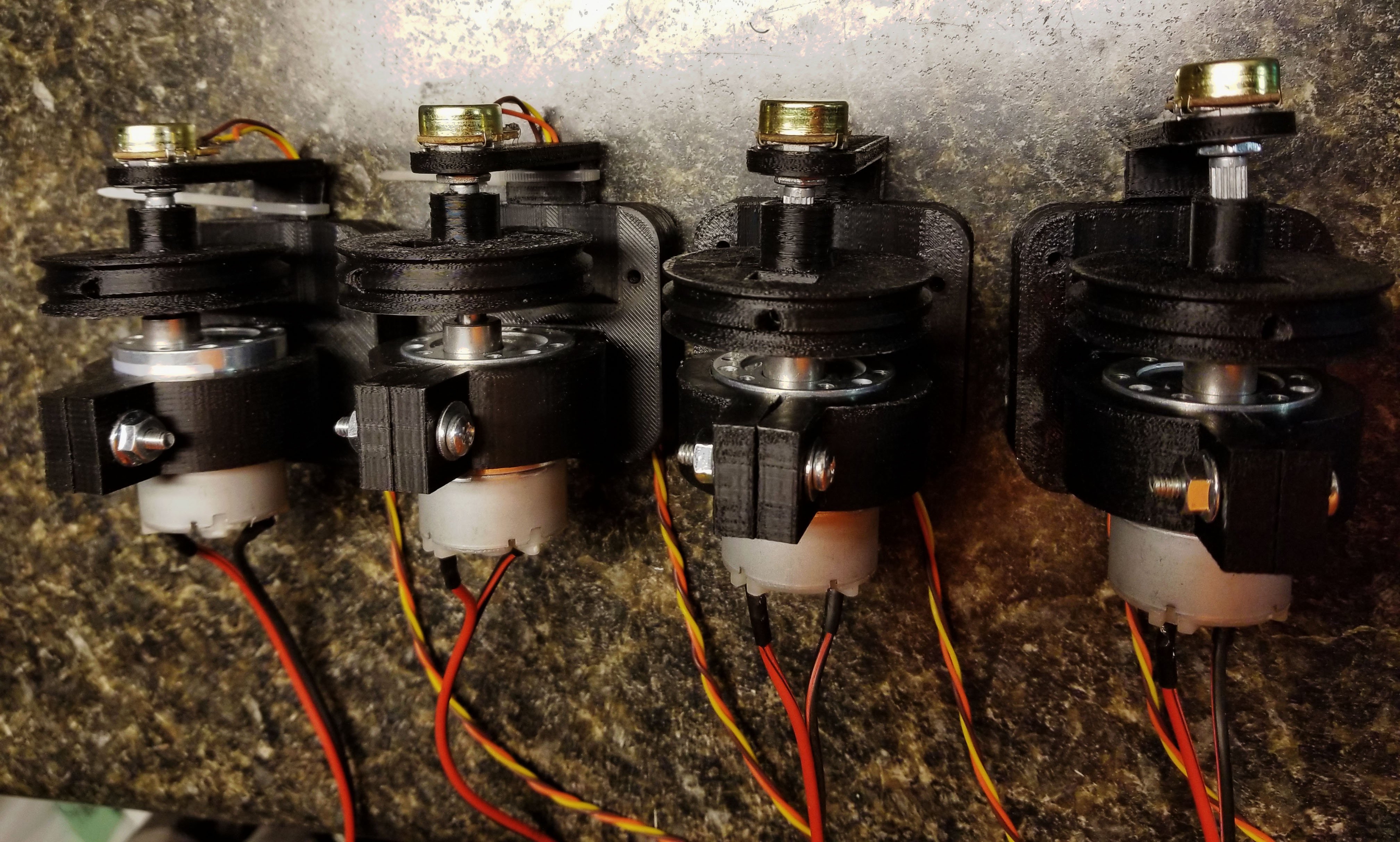
Here are the 4 main cable drive units. 12V, 60 RPM gear motors, with feedback pots. I may have to use 30, or even 20 RPM motors depending on the load.
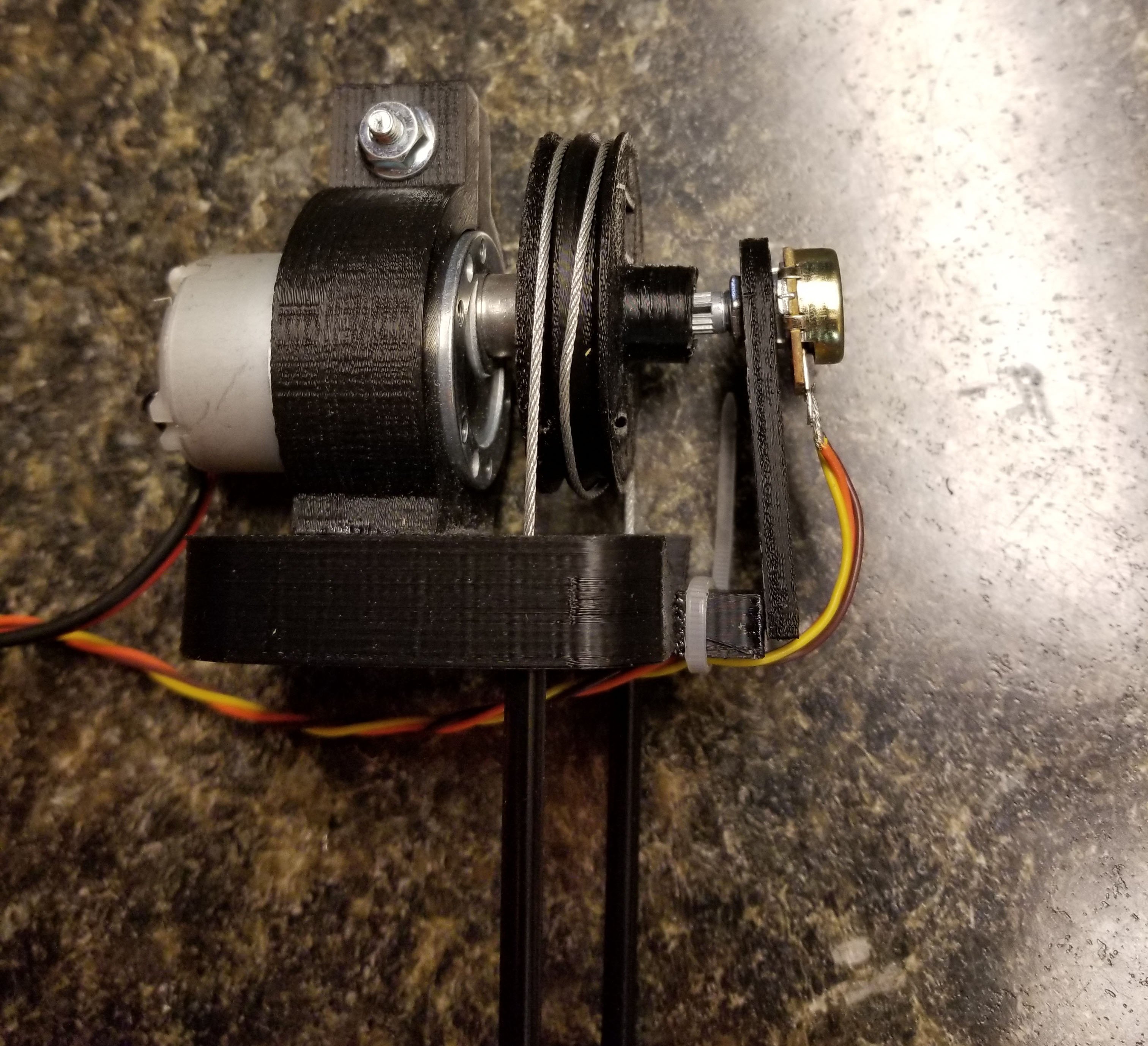
Closer look at the drive, with the cable and sleeves in place.
This is my miniature "input rig" I will use to directly input motion, or create a motion file that the Arduino will read and execute.
And last one for now. My 1st (bad) attempt at sculpting. I really need to ditch the styrofoam head and make an armature. But, I'm learning! This was more a test to see if I could do it this way. Um... nope. lol

I always welcome comments, questions, advice, constructive criticism, or even just a chat.
Take care all!
Post edited by Joel Goodpaster on
2
Comments
What is the attachment piece on the cable connecting it to the 3d print in your last picture?
I love working with cable mechs, but the attachment points for the housing or the cable are always a point of frustration for me.
/Chris
Another challenge I've been trying to address with my cable mechs is that having the controllers, cables, and character all permanently linked makes working on and transporting them a real headache. I'd love to find a way to be able to easily disconnect the cable at either or both ends. Ideally with some type of connector that does not limit mobility of the cables or introduce any slop.
/Chris
I've also had time to work on various parts of my project, and figured I would work on my (severely lacking) video skills.
First a quick test of the gear motor/ cable drive. I'm currently working on coding the Arduino so I can control the 4 actions.
Next, I tried my first go at silicone. I just made some test skins to get the 'feel' for it, and to have something to practice my painting on. My technique is not great, and I need to pay more attention to details. But, it is all learning...
/Chris
If anyone is interested in the file, I can throw it up on GrabCAD or something.
Last edit...promise.