OmniWrench Replica Prop Build – Ratchet and Clank
I grew up playing the Ratchet and Clank games on the PlayStation and decided to build one of the weapons from the games. I’m already in the process of building Clank (the small robot you see below), so I decided to create Ratchet’s OmniWrench.
The OmniWrench is the blue/silver weapon Ratchet is holding on the right. The weapon changes every few games, so I decided to settle on the current iteration which is dubbed the ‘Millennium 12’ OmniWrench.


To build this prop replica I’m using reference photos from the game to create 3D models in Autodesk Inventor. The Ratchet and Clank games are known for oversized fun weapons and gadgets, so I’m scaling my wrench to fit that category. From that, my OmniWrench will total 600mm/23.5 inches in length.
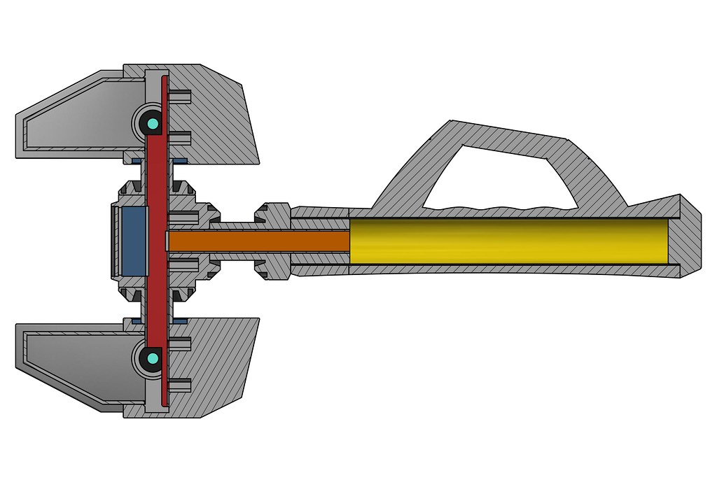
Since it’ll be a considerable size, I’ve designed my files to incorporate metal piping and steel tubing internally. This serves the dual purpose of reinforcing the prop as well as providing me hollow internals that I can run electronics and LED’s through. To jumpstart the process I started with modelling the handle and grip sections.


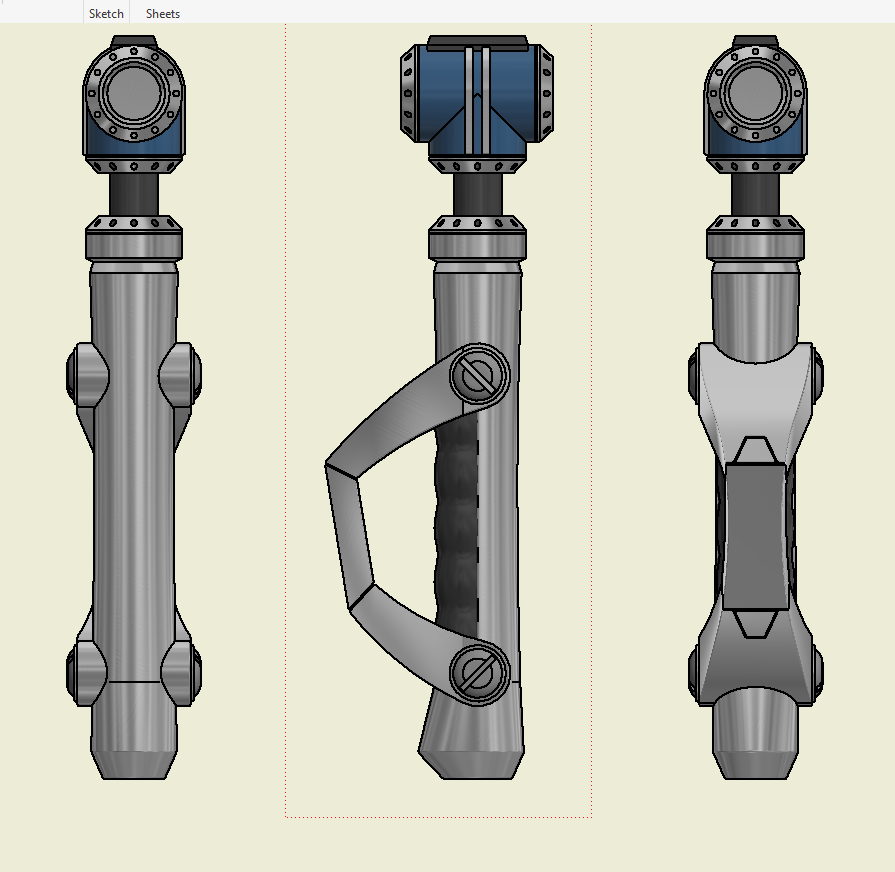


In the section view below you can the internals I’ve design to accommodate metal piping/tubing which I’ll run my electronics through.

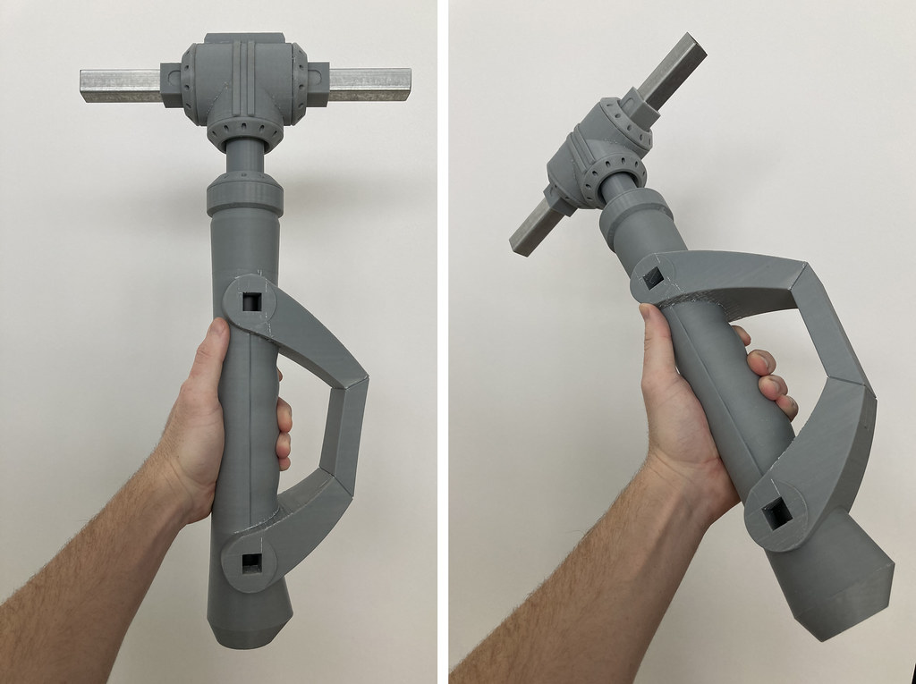
With the 3D model completed I was able to start 3D printing. I started with parts for the central junction area where that connects the handle to the wrench’s jaws.
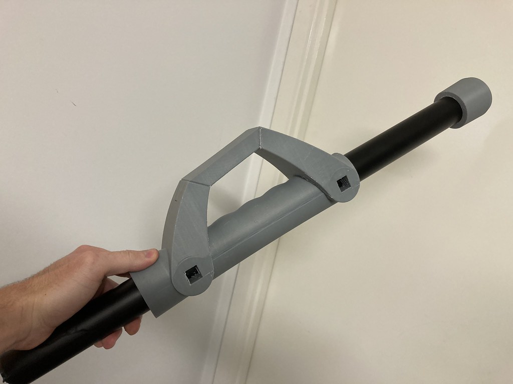
I designed the files so the parts resulted in a snug friction fit over the square steel piping. This way they’re on tight enough that they won’t come off by accident however I can still remove parts for sanding or painting individually prior to final assembly.

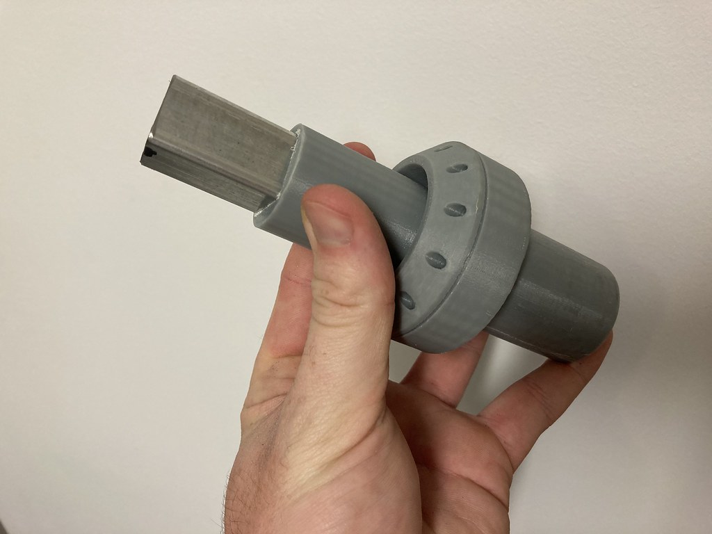
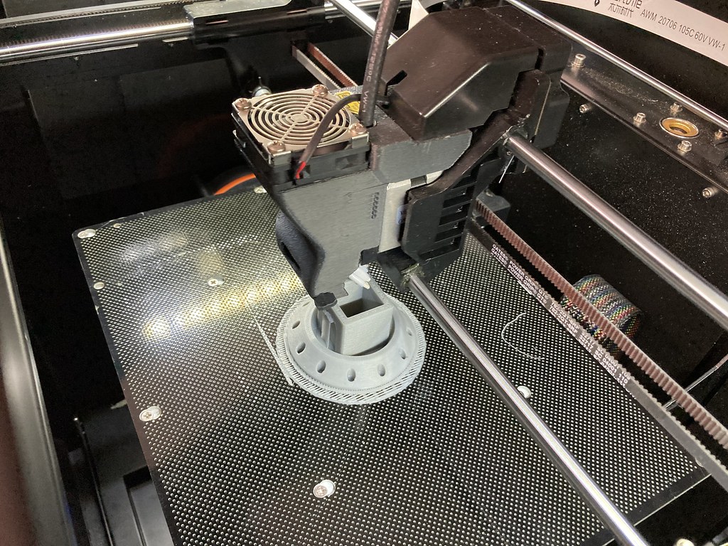


With the top junction area finished it was time to start printing the main handle/grip section. Once the handle was printed, I was able to sleeve it onto the metal pipe I’d be using to house the bulk of the electronics.
I also needed to fit a x4 AAA battery holder inside as my power source. I was able to find a metal table leg at Bunnings that was the perfect diameter to accommodate the battery holder whilst fitting inside the printed parts.
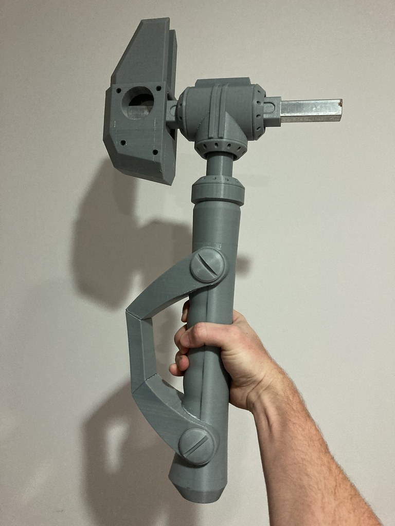


With nearly all the parts printed I was able to begin prototyping a solution for lighting the jaws of the wrench. Initially I was looking at LED strips, however the uneven distribution of the lighting wasn’t ideal.
After research into alternatives, I settled on Electroluminescent Tape. The Electroluminescent Tape is great since it provides a nice consistent lighting source. It’s also flexible and I can bend it up to 90 degrees, the only downside is it isn’t as bright as LED strips.

To mount it the LED strip in the jaw area I printed a thin profile that’s a nice friction fit. I then used strong double-sided tape attach the Electroluminescent tape.


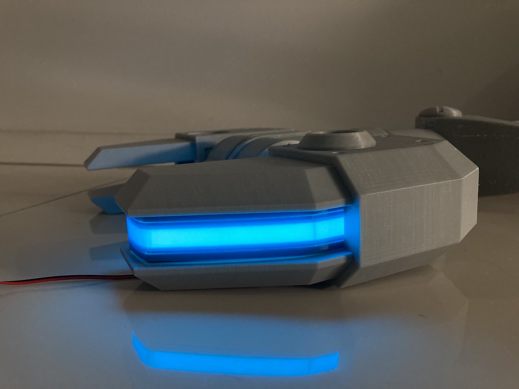

With the Electronics prototype sorted I needed to make the steel piece that connects the two jaws to the handle.


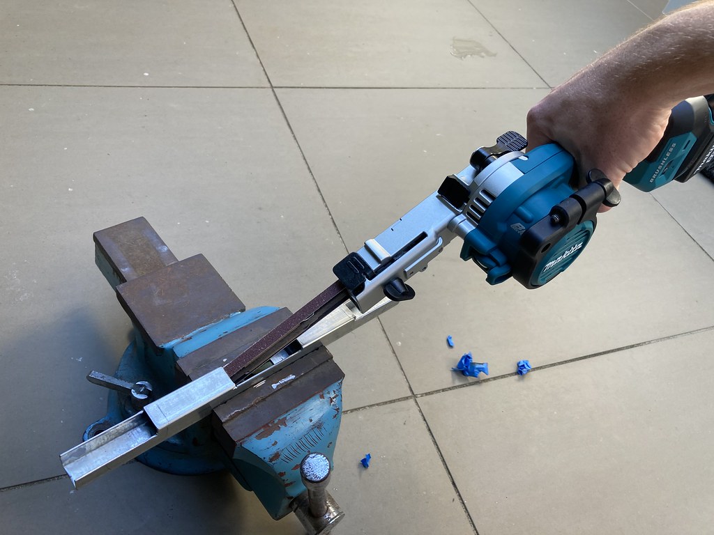

With the steel piece completed it was time to prep the jaws with threaded inserts.
I drilled holes in the steel that line up with threaded inserts inside the jaws. Then when I sleeve the jaw onto the steel, I can thread a bolt through securing the two parts together. This allows for a solid assembly that I can still disassemble for working on maintenance on electronics or for painting.
When I 3D modelled the jaws, I designed cavities for M6 coupling nuts. The tolerances were designed such that I needed to hammer them into the hole resulting in a very secure fit. I also made sure to increase the infill of the 3D print to make sure that nothing buckled when hammering the nuts into place.


Comments
/Chris
I used my grinder to quickly cut some channels/grooves into the 3D print. These grooves allow the glue to seep inside and help increase the reliability of the bond between the two parts as the Z Poxy as it has more to grip onto.
With the two halves glued together, it was time to start the process of creating my electronics setup.
To light the circular windows, I’m using 10mm blue LEDs that are friction fit into the opening in the rear of the bezel. This sub assembly can then be inserted into the side of the jaw with, yet another friction fit.
The blue lens seen inside the bezel are cheap Arcade style buttons that I gutted for the lens and diffuser.
I also printed out the fake bolt/rivet heads that are seen on the prop in the game. I designed these so that I could fit them after the fact to help make the sanding and painting process easier.
I also needed to install the EL Tape in the top window that sits between the two jaws.
The central junction piece on the prop has a lip that I incorporated into the design that helps fit another little 3D printed mounting plate that has the EL Tape. The plate is inserted into the gap and the lip prevents the plate from going too far.
Once the 3D print plate and EL tape were in place, I was able to insert the blue diffuser.
/Chris
This as a real work of art both in design and execution. Please - show us some pictures of it being used.
/Chris
And here it is, the completed prop! To say I’m happy with the result would be an understatement
/Chris
And then here's some behind the scenes photos and close ups:
Great commercial too!
/Chris