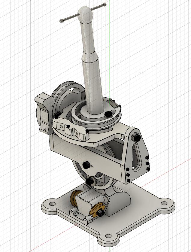
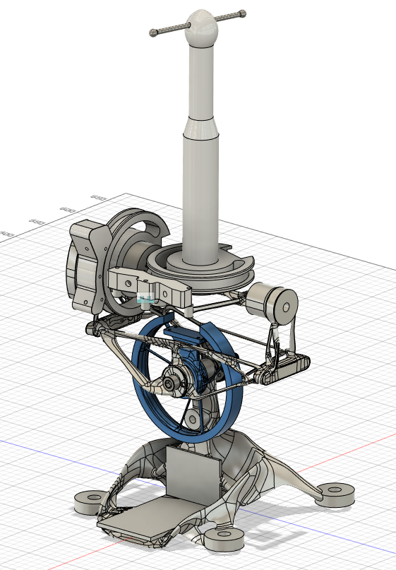
Cable controller CAD project
I just started working in CAD over the summer and decided to use the 3 axis puppet controller (from the tentacle mechanism course)* as a final project for my intro to cad course. While I got a perfect score on the project, I for the life of me couldn't figure out if they had bearings in them or if they are metal on metal gliding pivots. I am on to my second design of the controller and was wondering if I could get some information on how that articulation works.


Post edited by Justin Baker on
1
Comments
I believe the controller we have (which this is based off) does have bearings. I don't have access to it right now though. I do know that if I were designing it I would 100% use bearings, as any friction is going to be working against the character's performance.
/Chris
I think my end goal is to take the generative study and design a sheet metal-based version with an I-beam structure. That design could be made with a simple plasma torch and welder versus having access to a mill and be close to the same weight as the generative controller.
I am going to go back and add some bearings into it. I thought gliding articulation sounded weird for a puppet controller but not having it in my hands, I had to make some guesses.
-Justin
Expense is also a concern, as the billet size for the milled part would be a lot of aluminum!
/Chris
Thanks for the information about the bearings, maybe I will actually build one of these designs in 2020. ^_^
-Justin